No pictures were taken for the first couple of years, unfortunatley.
2019-2020 school year
Project is discovered, permission is gained to "have at it" and figure out how the robot arm works.Once the arm has been rendered re-operational as its designers intended it to be, it is realized that the control system is so outdated as to be nearly unusable.
Planning is started for how to convert the arm to a new control system.
2020-2021 school year
Not too much tangible progress this year, partly due to extremely limitations on time in the lab due to shudowns and quarentines.However, the method for controlling the robot arm is prototyped, and most of the framework for the code is written.
Additionaly, later in the year, a prototype base is welded out of steel box tube, and re-wiring of the robot arm begins.
2021-2022 school year
A base is built out of an old belt sander's pedestal and some very large box tube, with caster wheels bolted on.First picture!
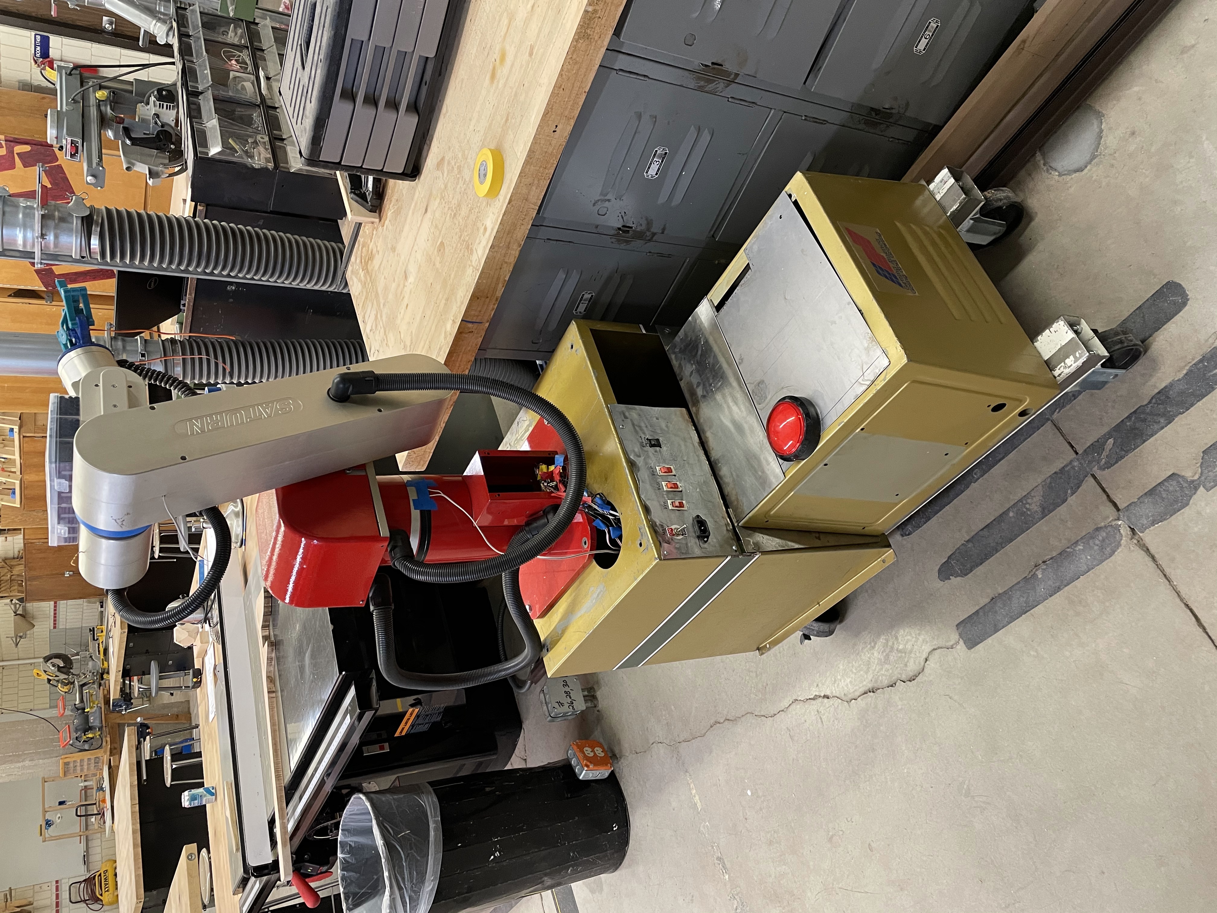
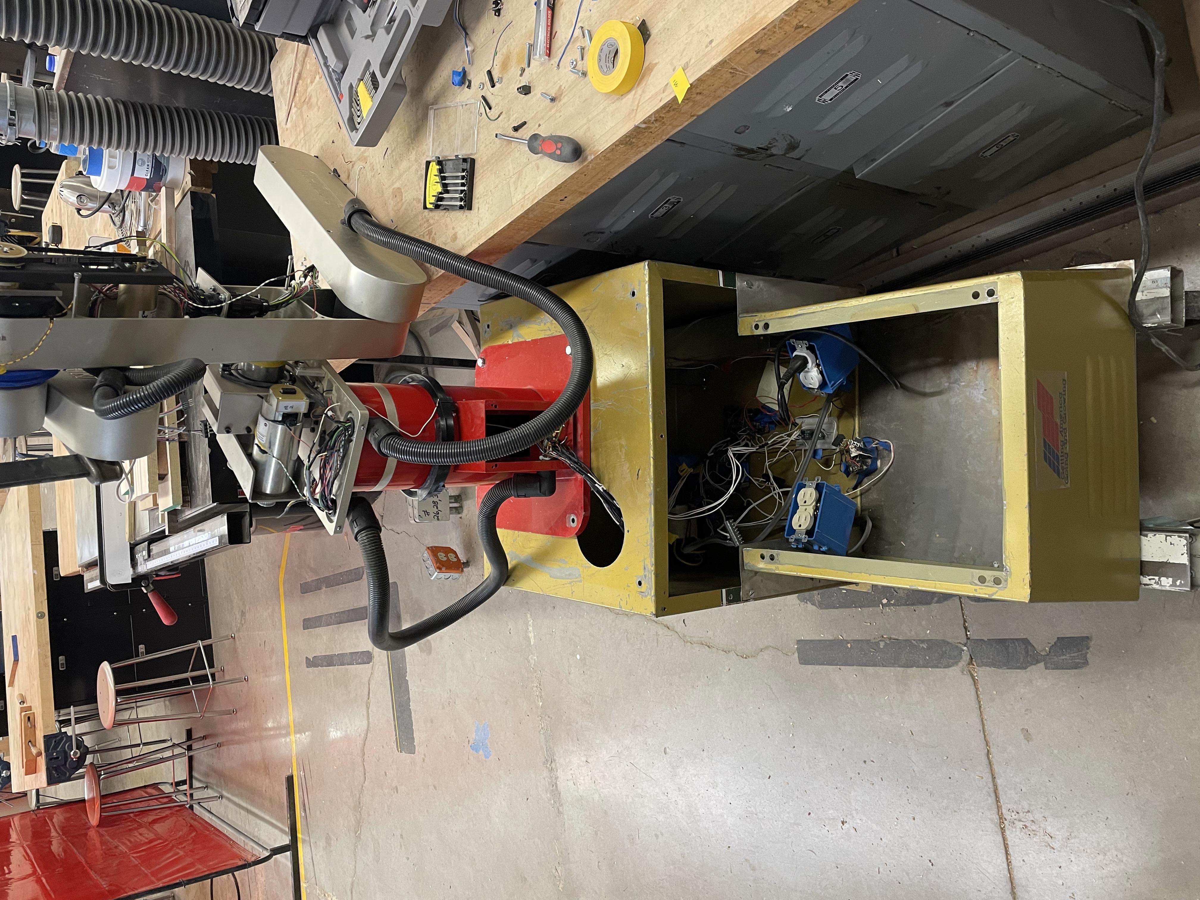
The power conversion components have been installed inside the box, and the front switch panel has been wired up.
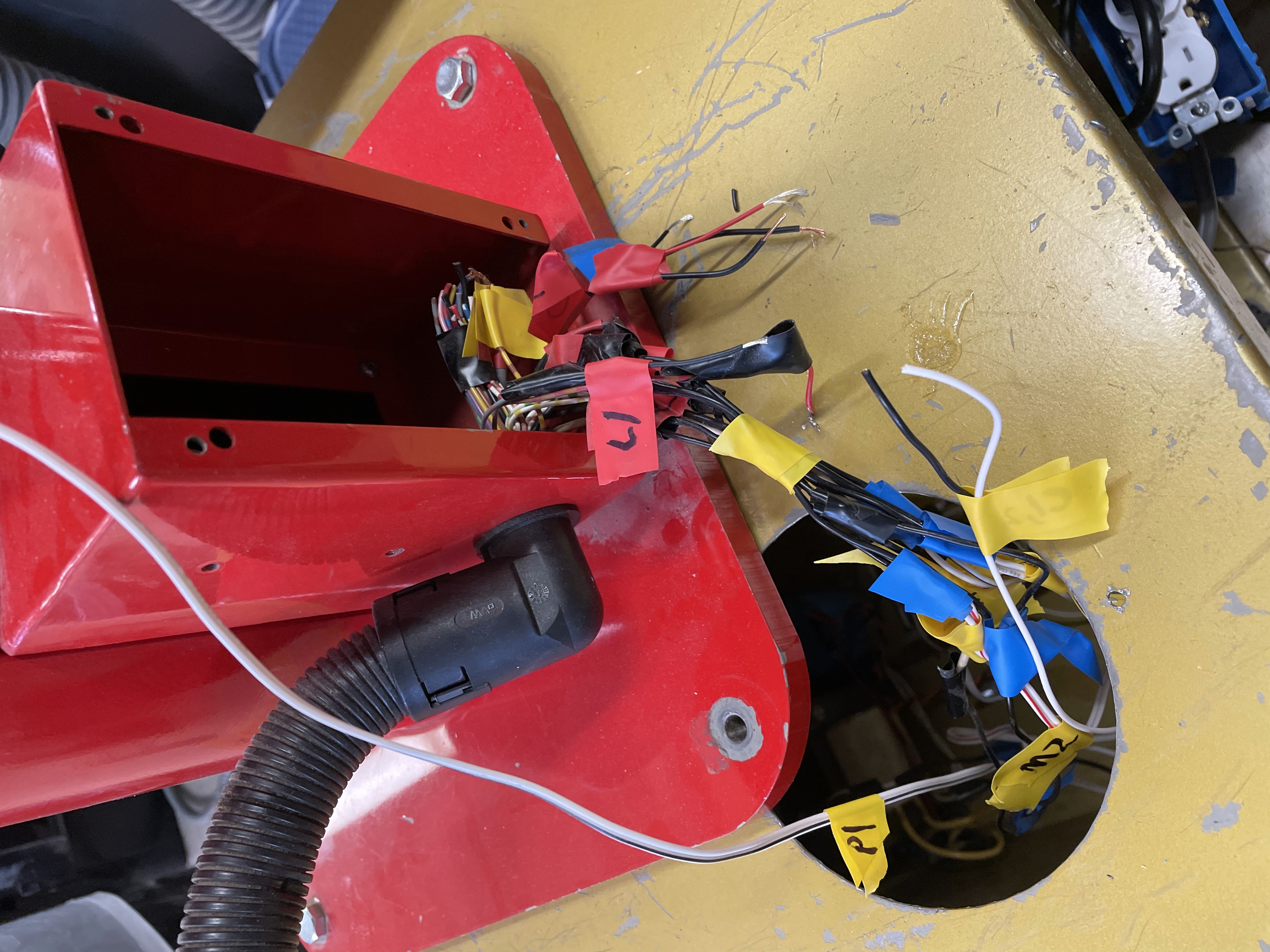
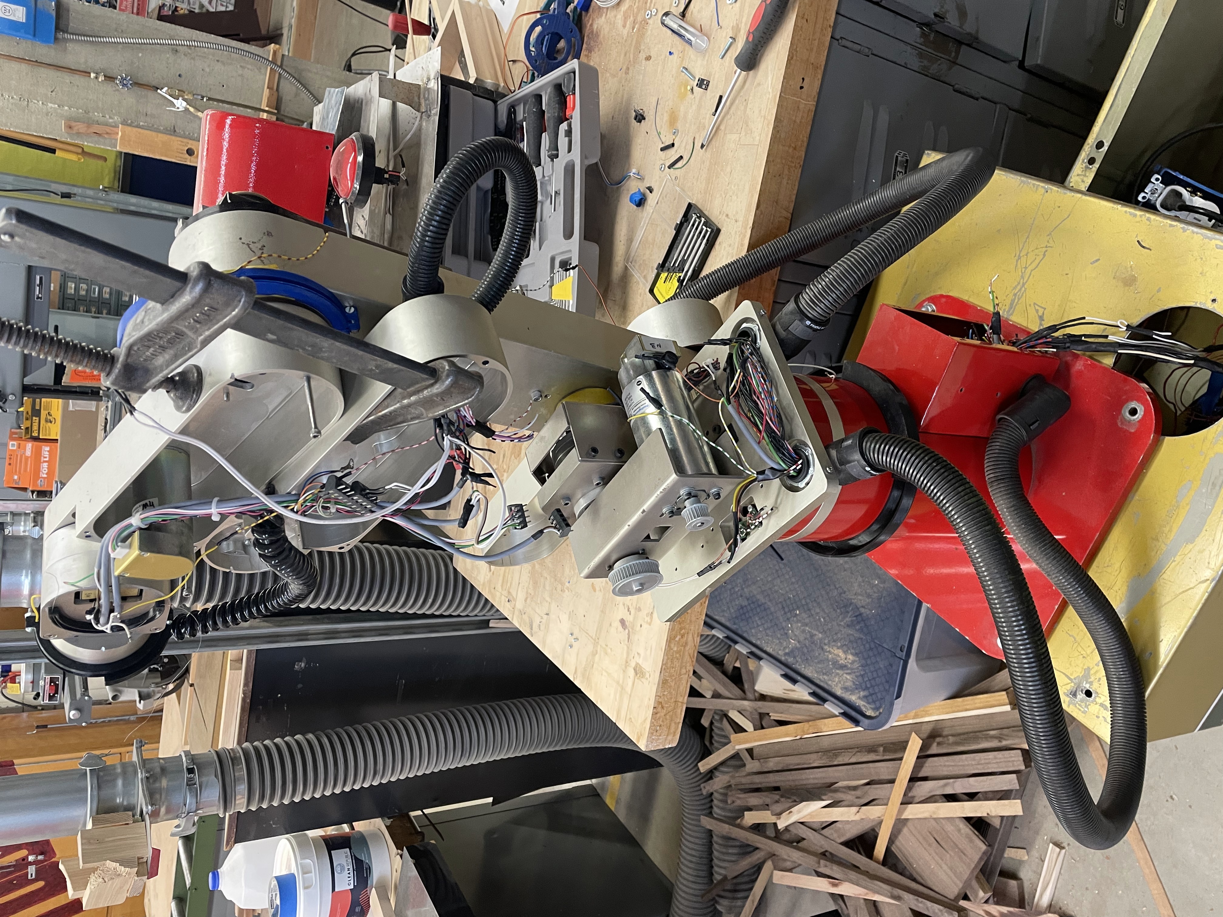
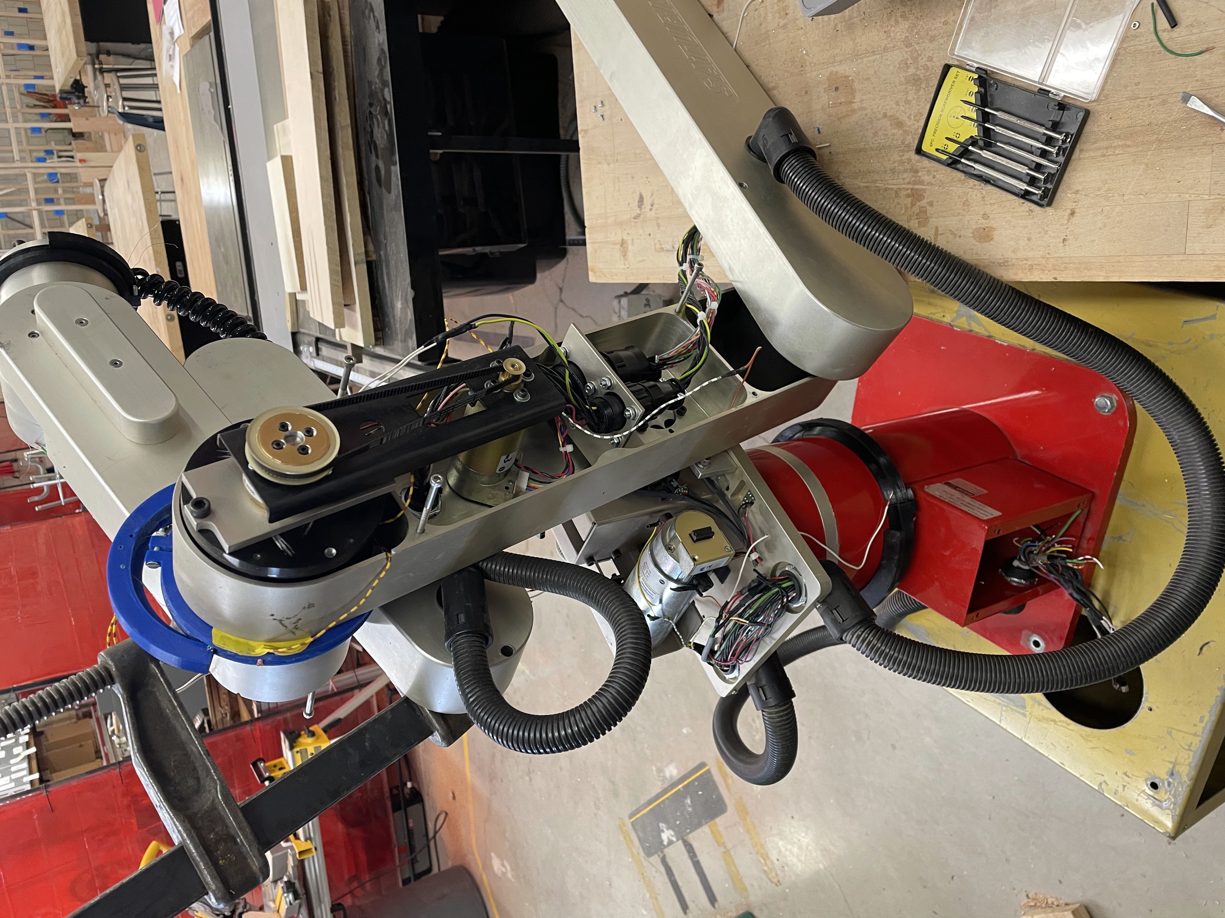
In the picture, we can see that connection of the wires from the robot arm into its base has begun.
Later, these will be managed with heat-shrink tubing.
Before this picture, some prototype sheet metal button panels that were manufactured to hold power switches and a temporary emergency stop button.
The picture shows the 3D printed nonfunctional prototype end effector (hand) attached to the end of the robot arm, in addition to the beginnings of a closed loop
feedback system on the trunk of the arm, attached with blue tape. This was simply for a proof of concept for the closed loop control, as the original system
for controlling the arm was based off of encoders and dead reckoning.
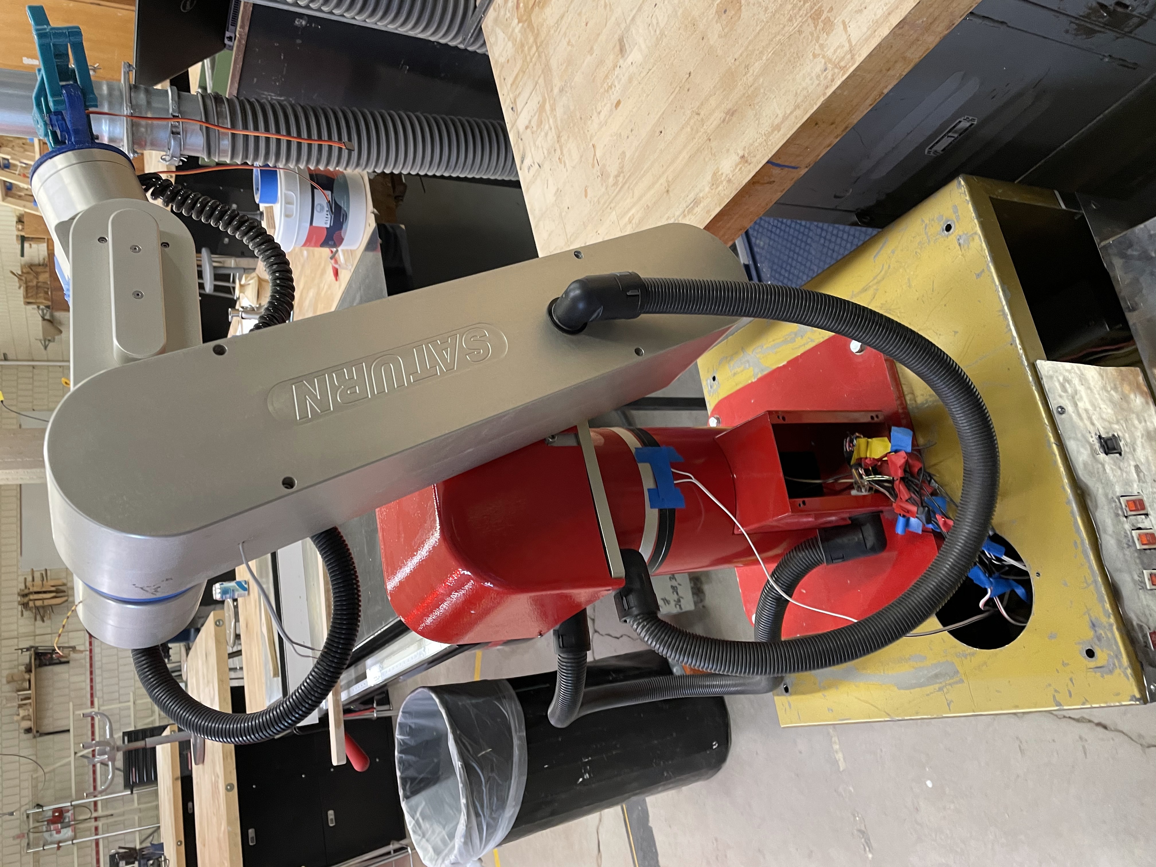
This picture shows the switch panels somewhat better.
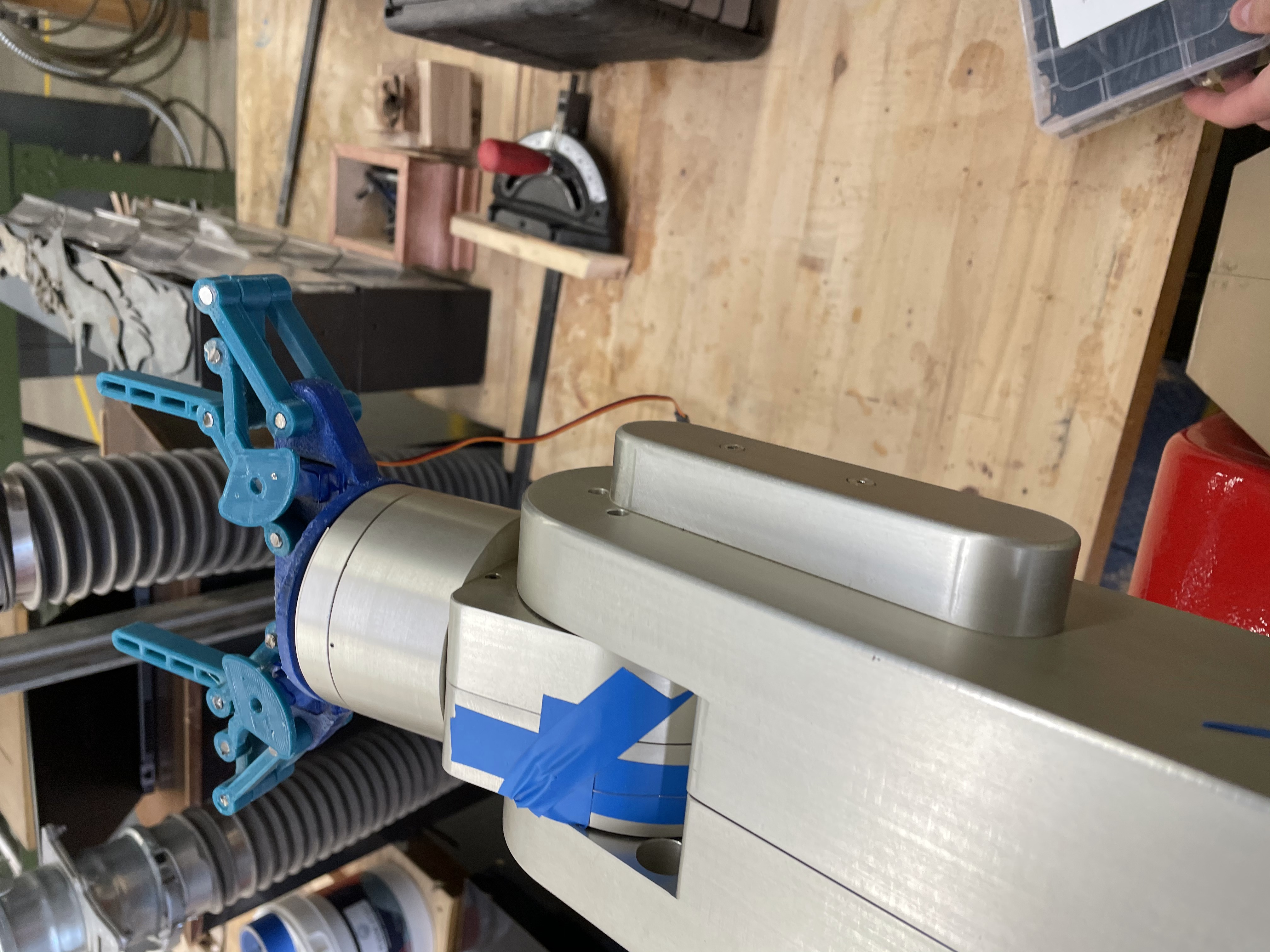
This picture is a close up of the wrist and hand assembly, with some tape to hold the prototype feedback wire.
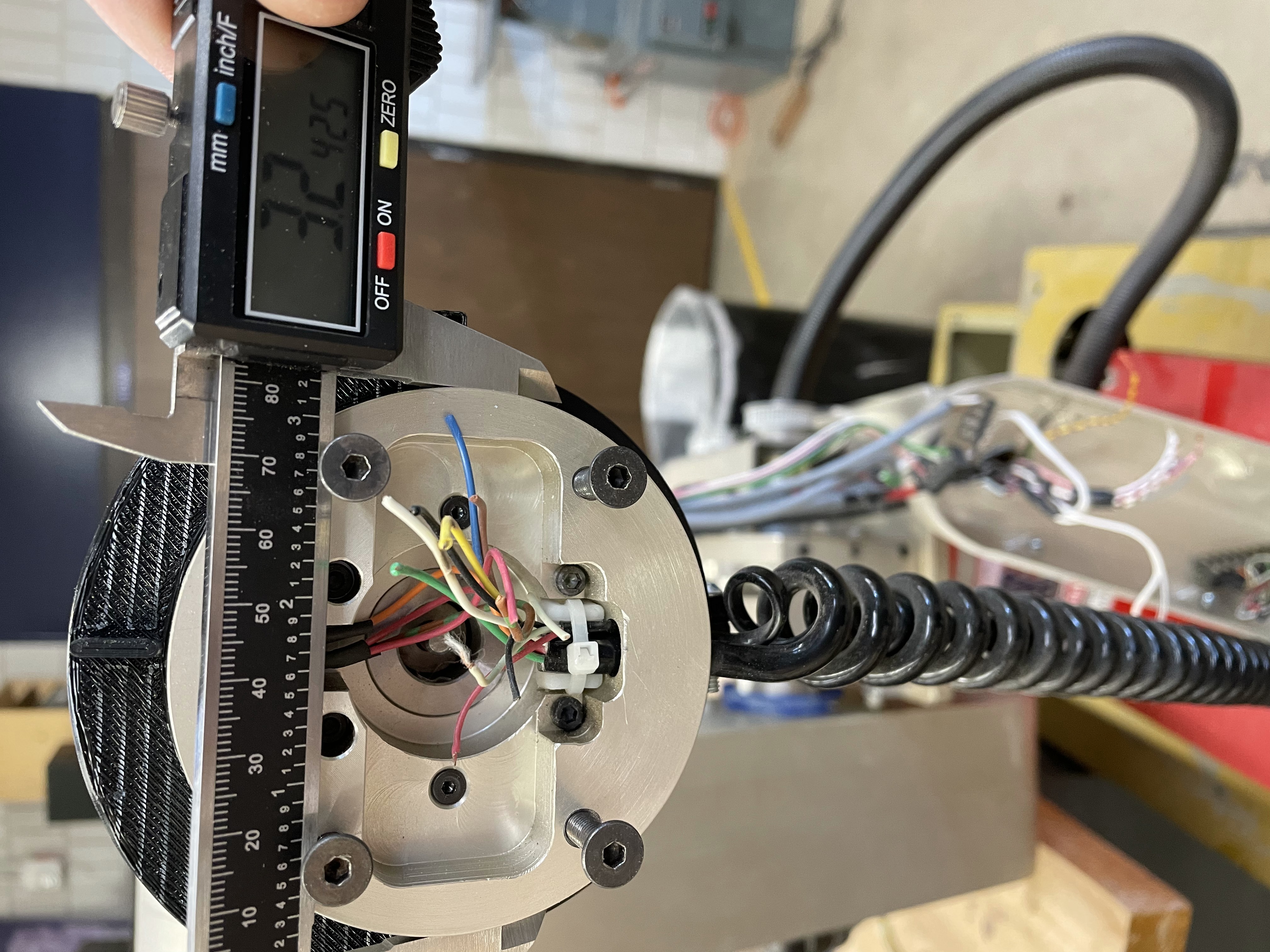
In this picture, in addition to a measurement for future hand attachments, the 3D printed retainer for the wrist rotation feedback wire can be seen, in black behind the calipers.
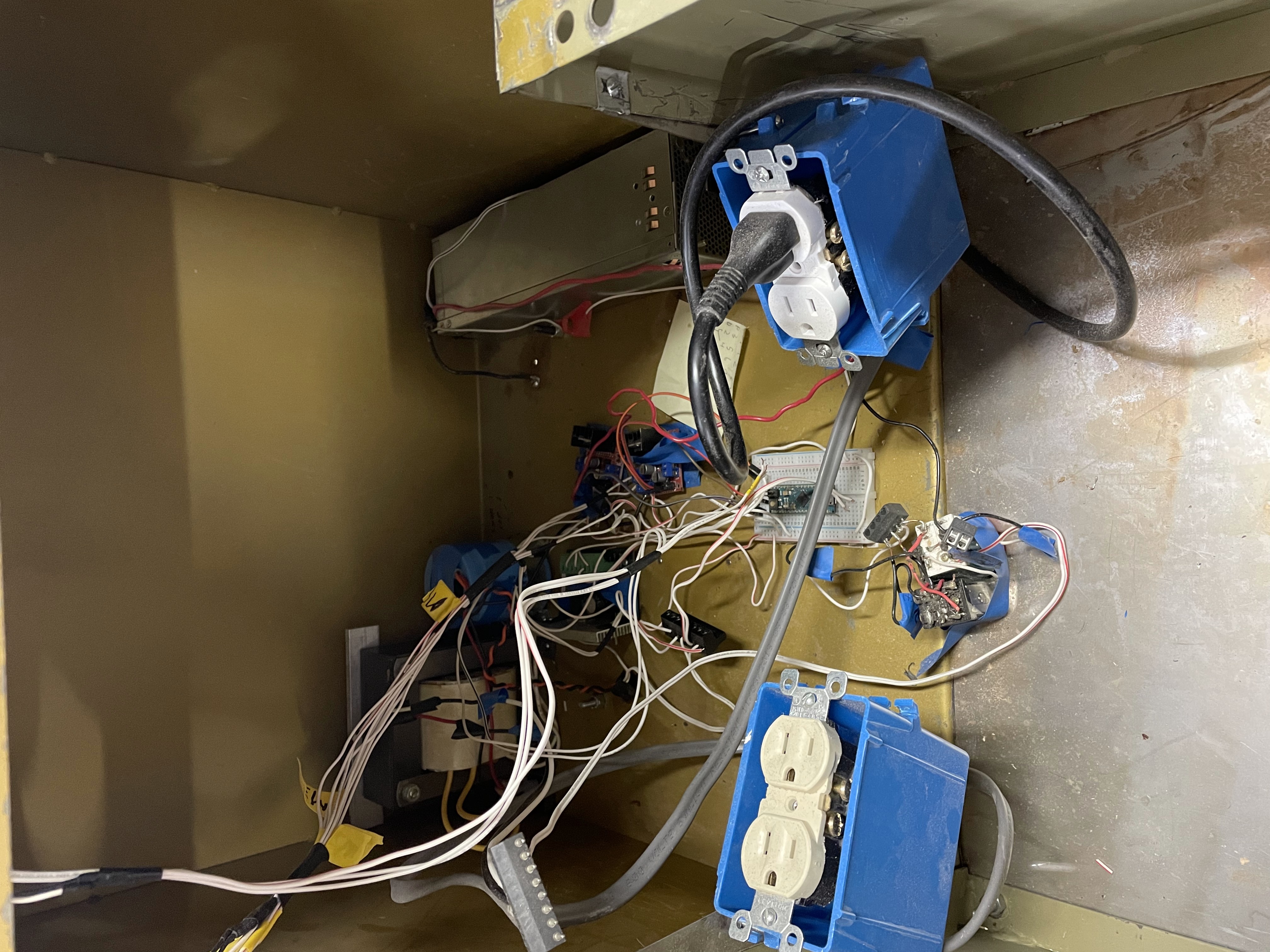
The innards exposed! If you look closely, you can see the connector for the front panel dangling in midair on the left, as the front panel has been removed. Three of the motor control boards
are temporarily attached torwards the back, in front of the transformer and capacitor for motor power, and right next to the modified server power supply for logic power and auxiliary 12V.
In front of the motor control boards is a breadboard with the arduino micro which controls the arm seated on it. This breadboard is mainly serving as power distribution at this point.
In the very front of the picture is the pair of relays serving as the emergency stop logic, which shut off all power to the system when one button is pressed, and restore it when another
is pressed. This is not ideal, and will be replaced with a true emergency stop button.
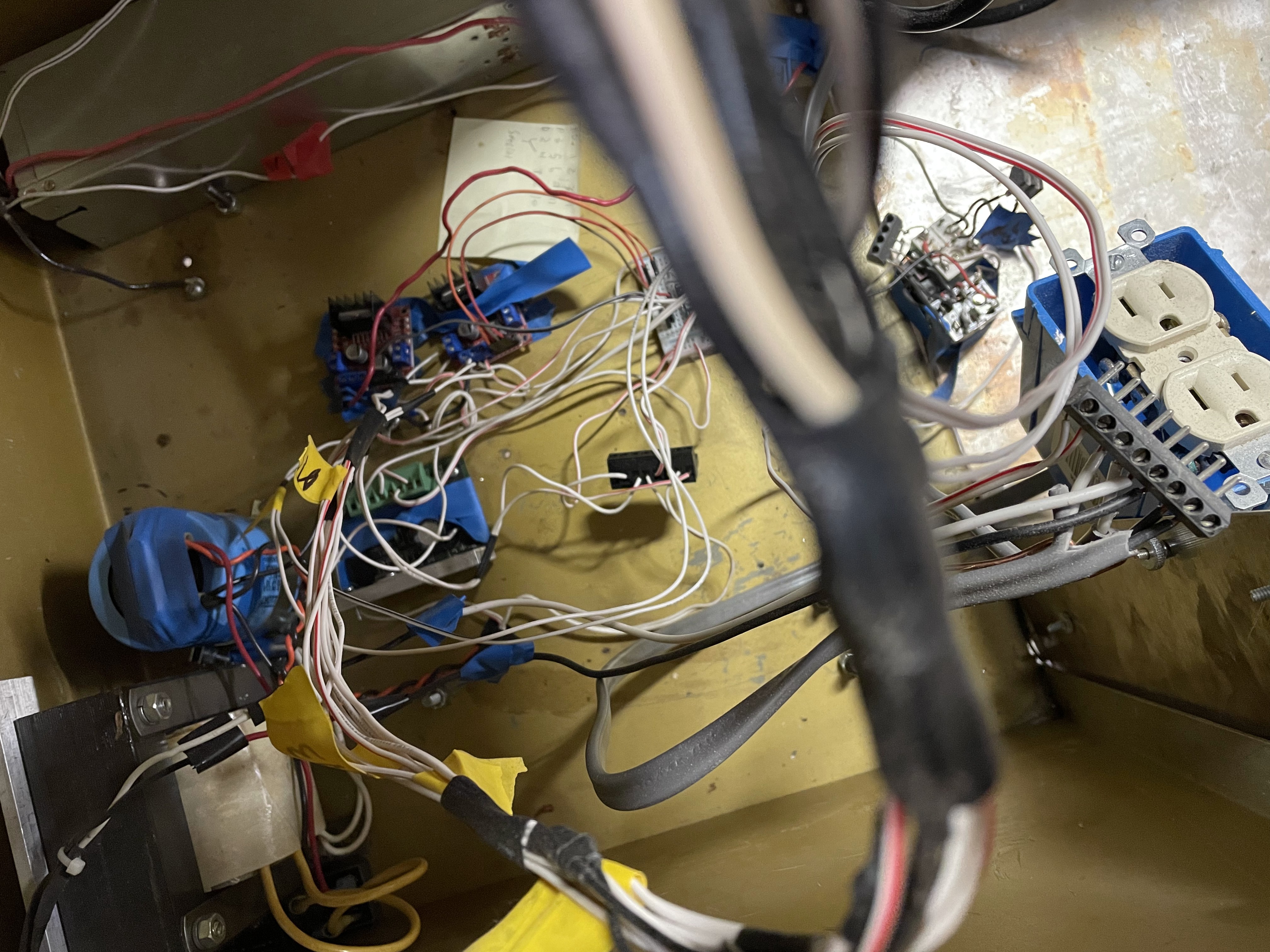
This is a top-down view of the same scene, with the large cable of wires running to the robot arm going right across the front of the picture.
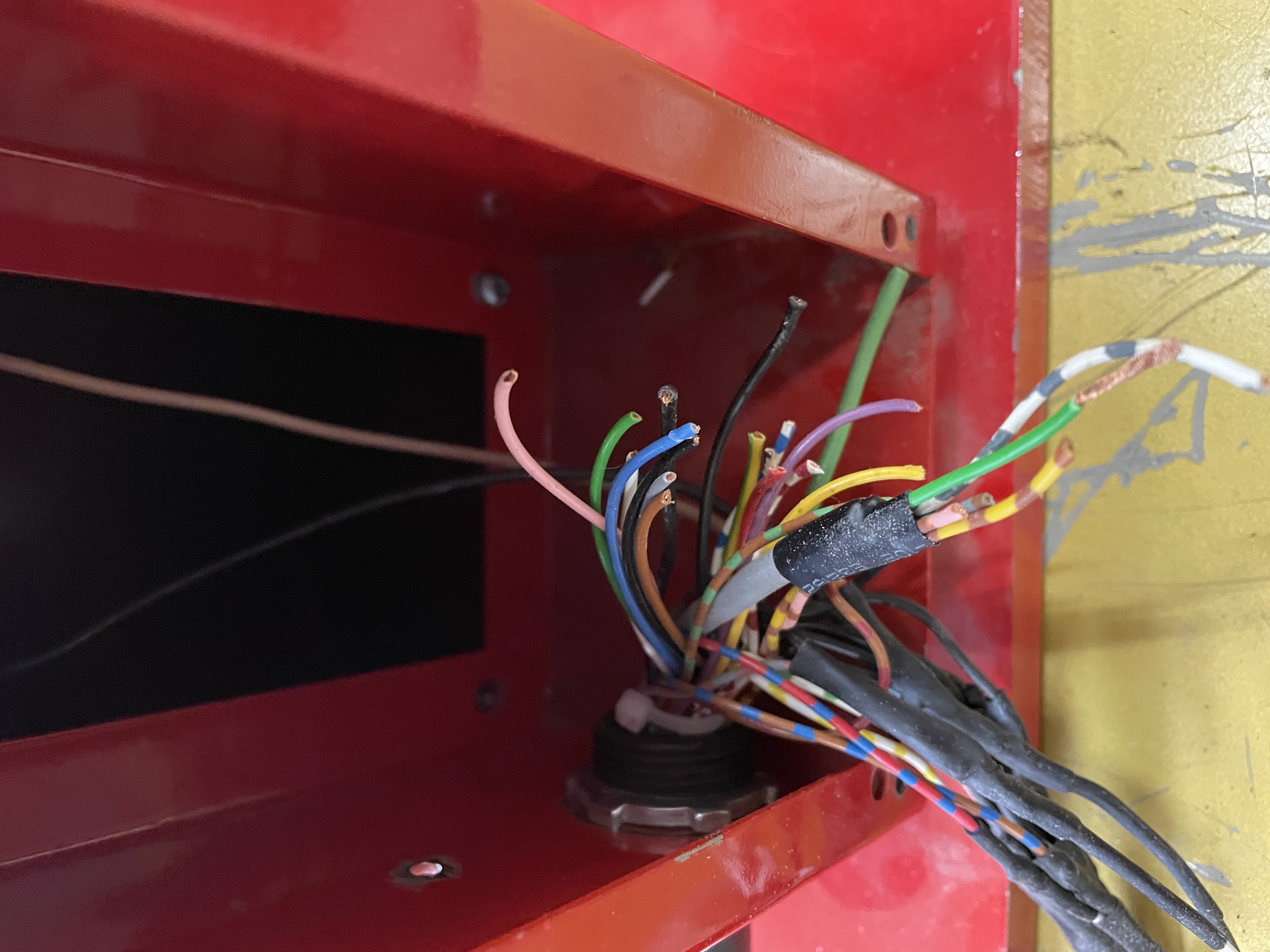
Finally, heatshrink tubing has been added to clean up the junction between control box and arm!
The next couple of pictures show the insides of the robot arm, as work is being done to wire it up for the prototype potentiometers, which are the
brightly colored 3D prints attached to some of the joints of the robot arm.
The control box all emptied out, with standoffs mounted in preparation to recieve the circuit board!
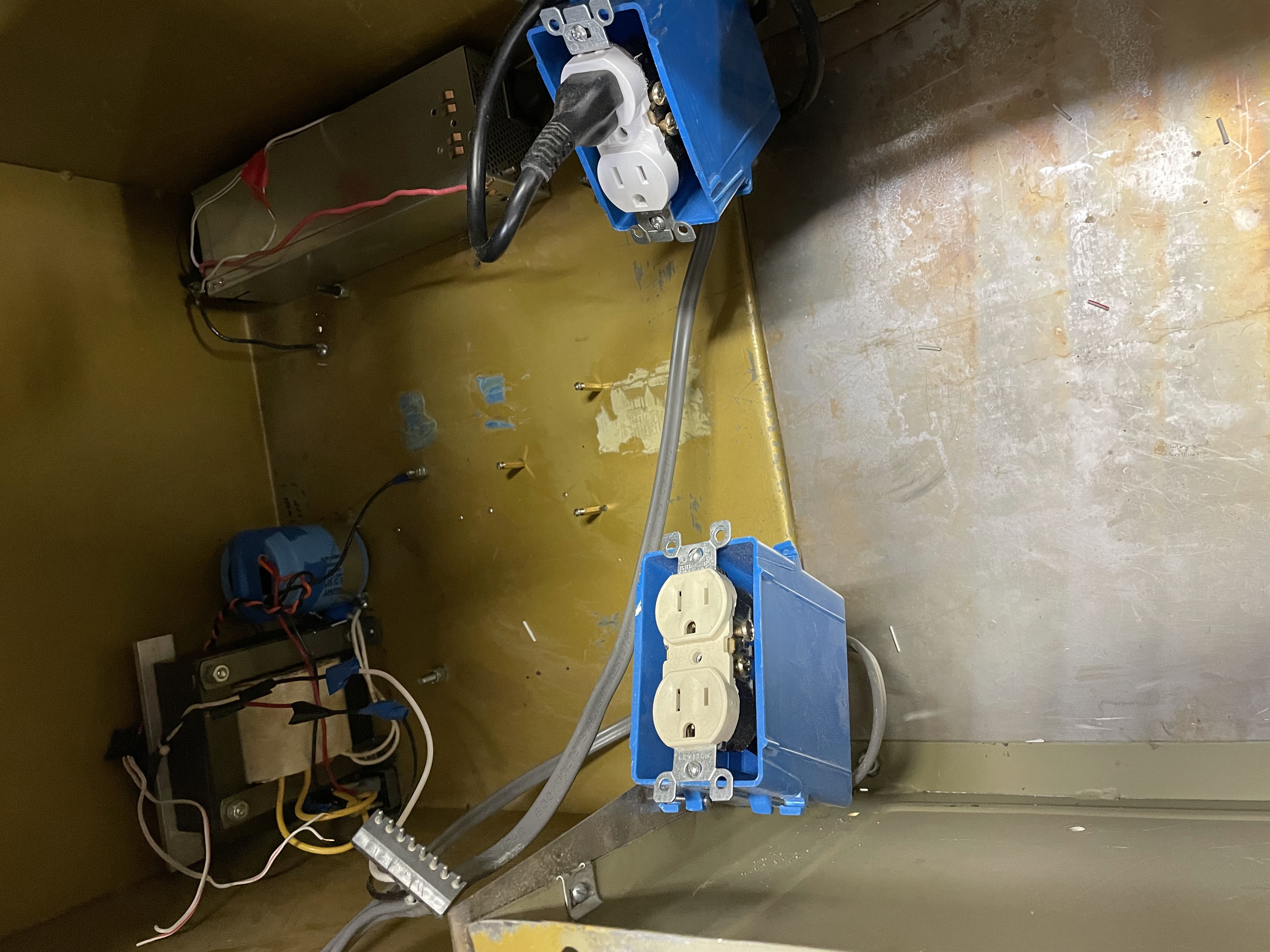
A circuit board was designed and ordered with JLCPCB, who manufactured five boards and assembled two of them. They are beautiful. Fronts and backs of empty and assembled boards:
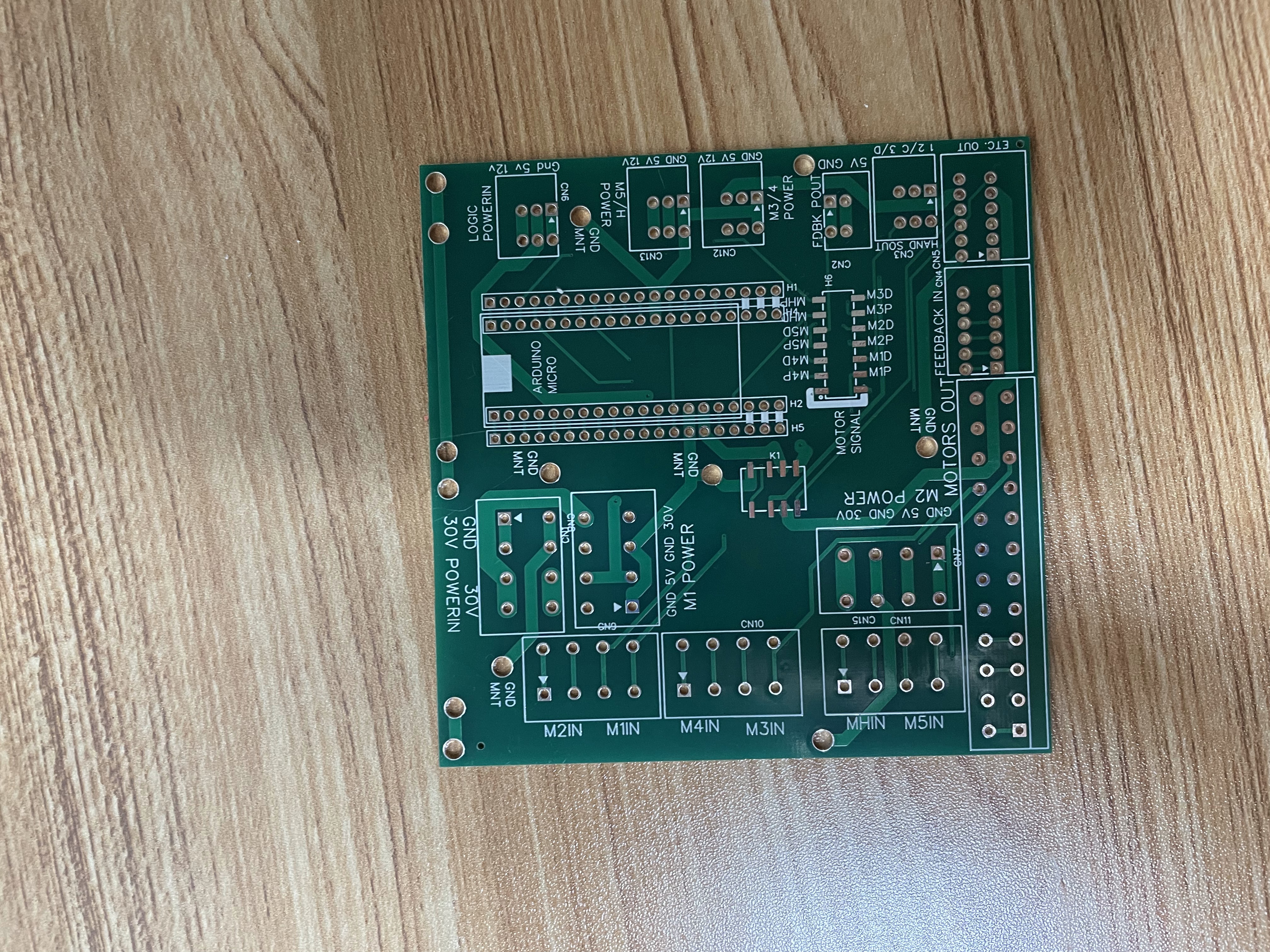
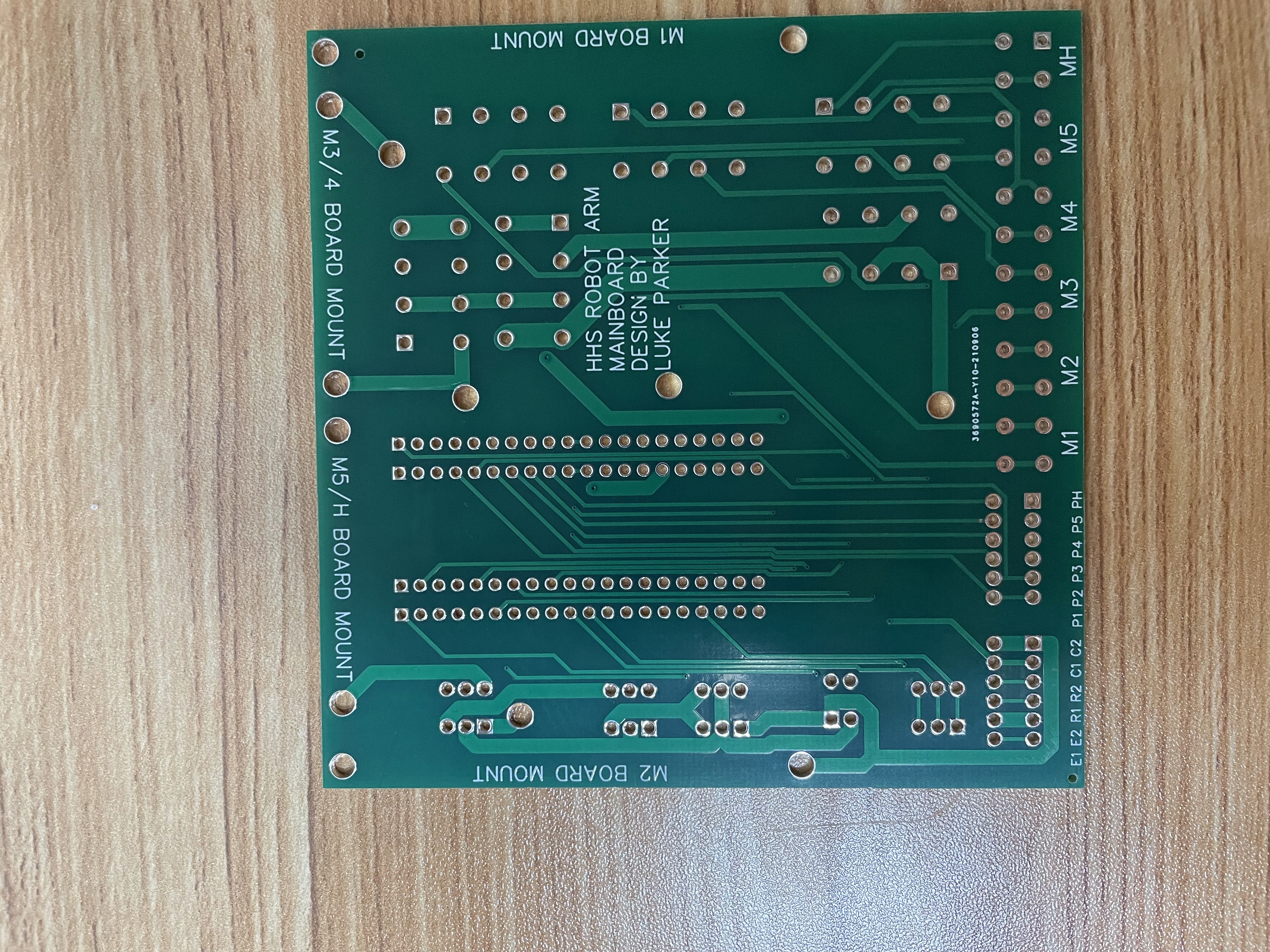
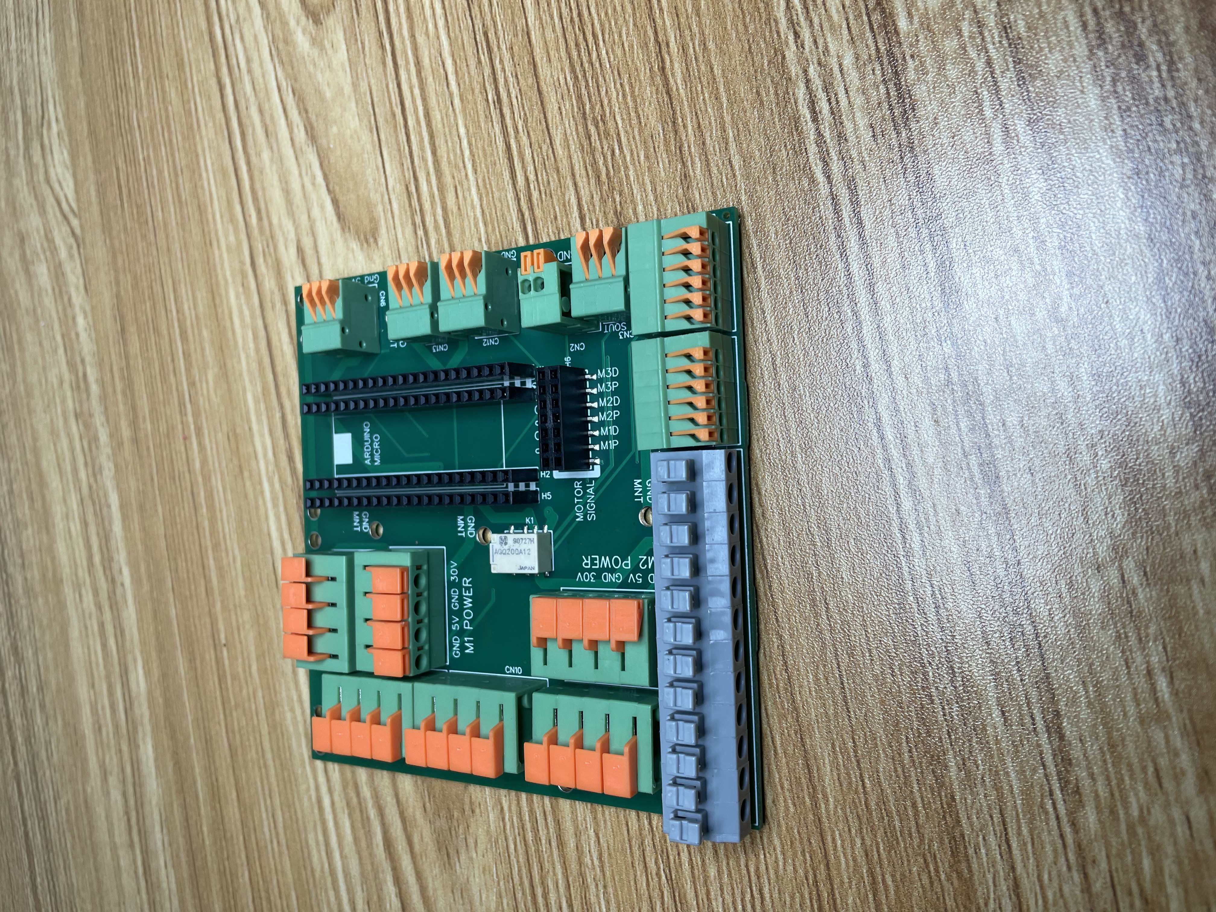
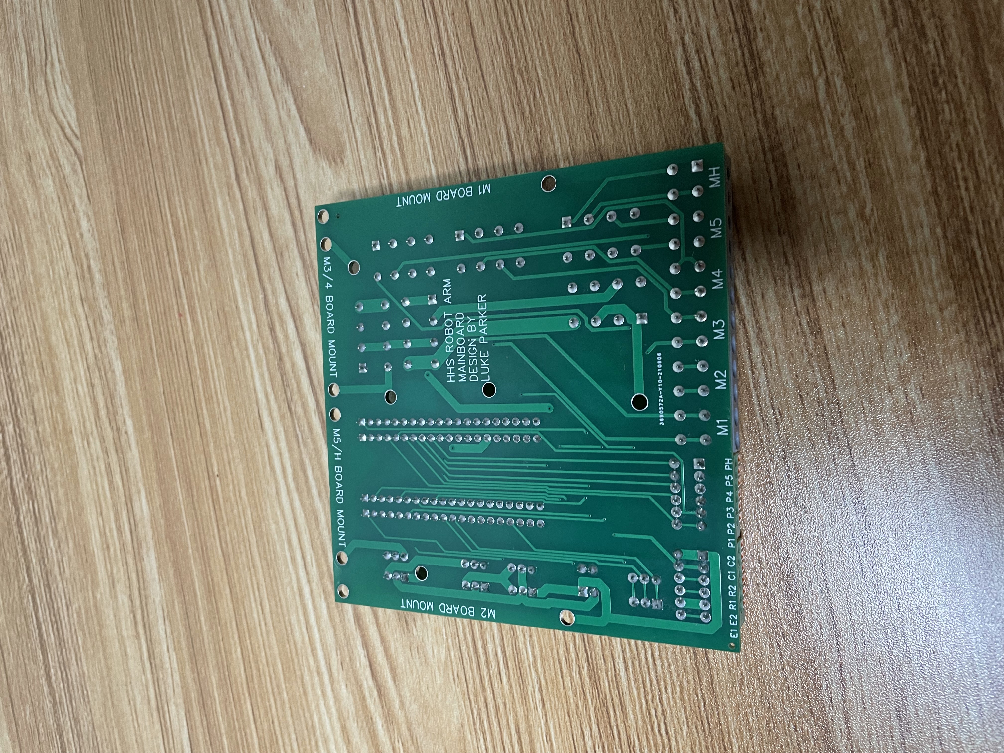
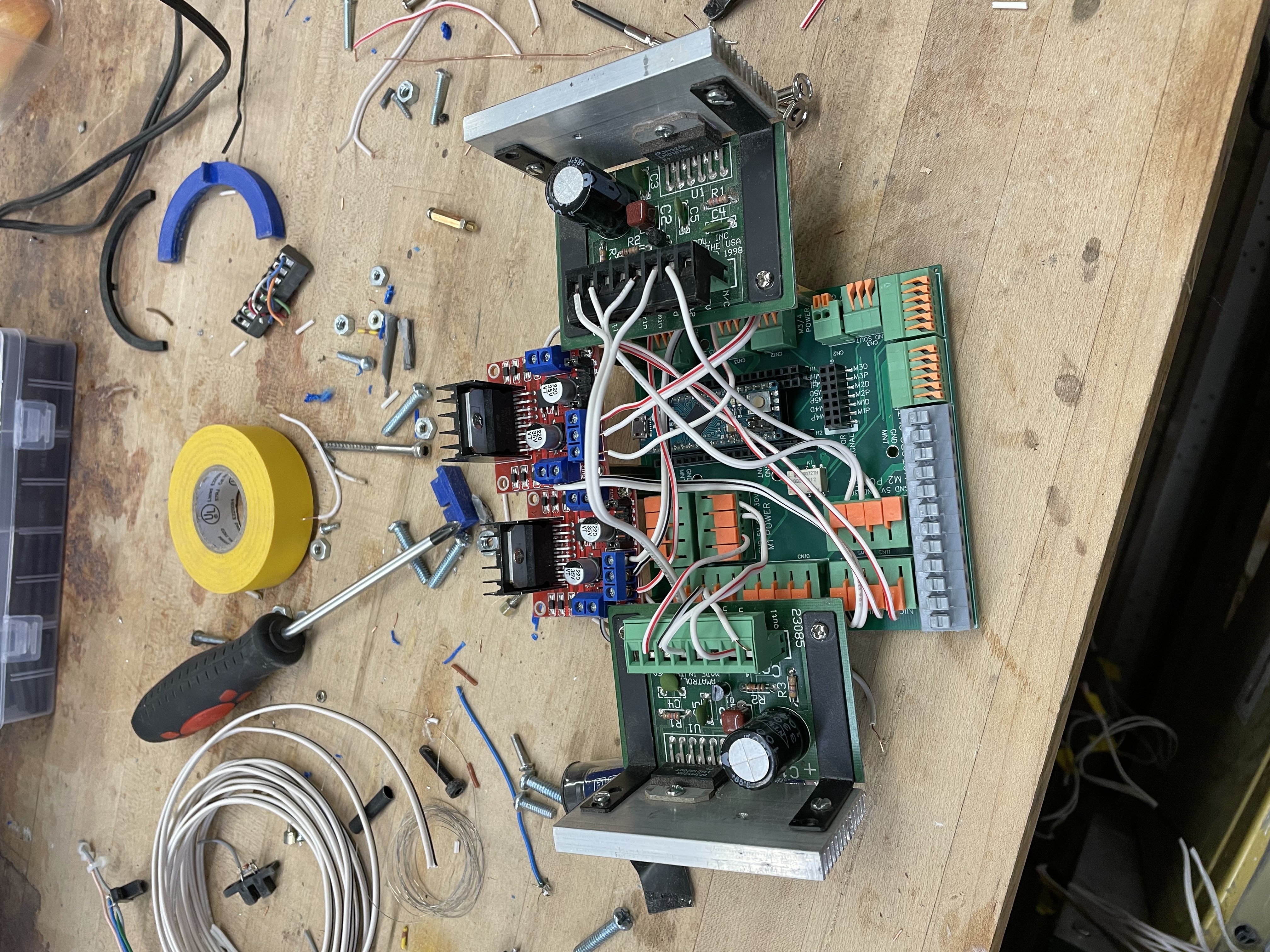
Here is the board with motor drivers attached, the arduino micro mounted, and everything all wired up!
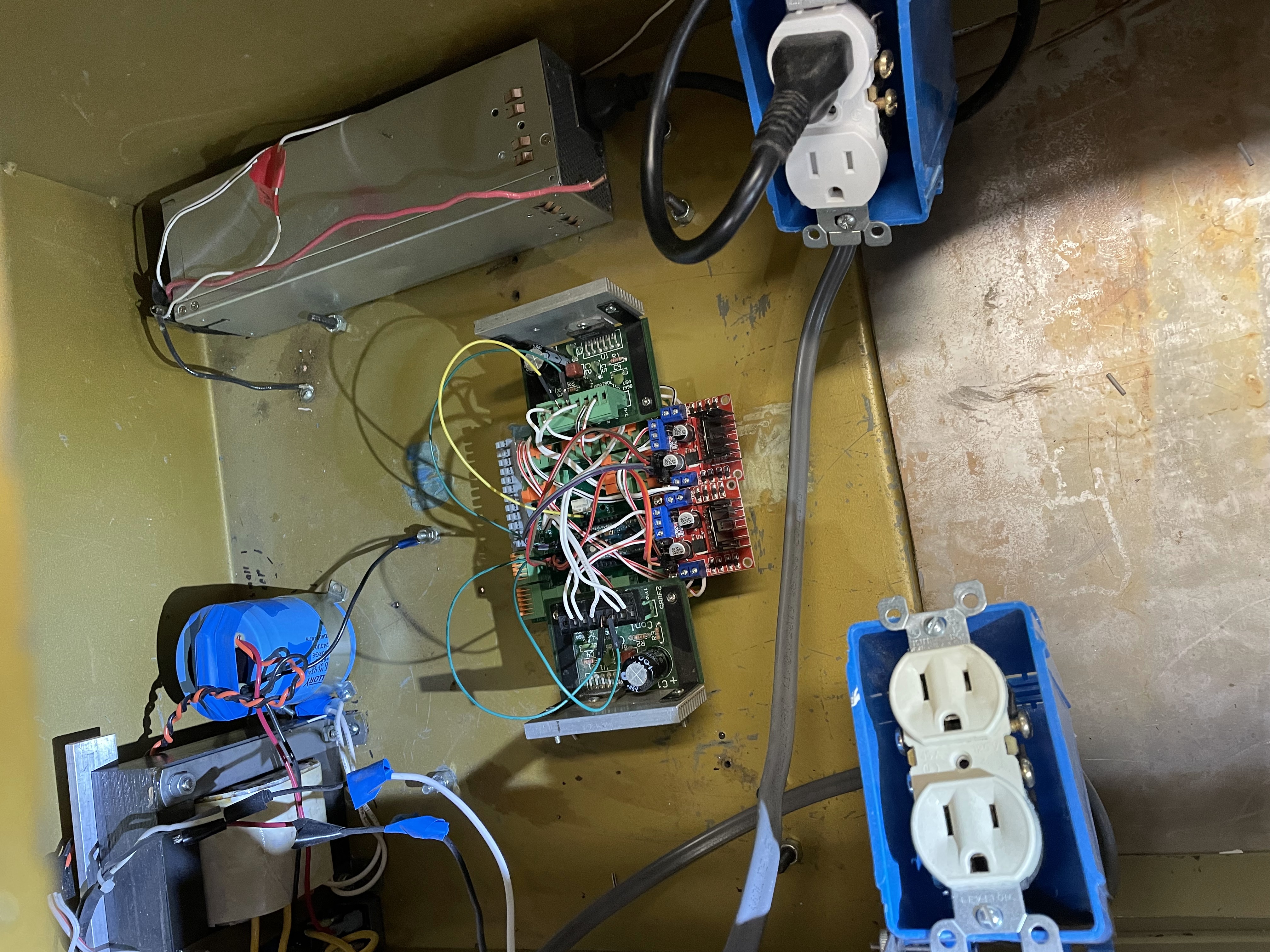
The board installed, ready for wires to the arm above to be connected!
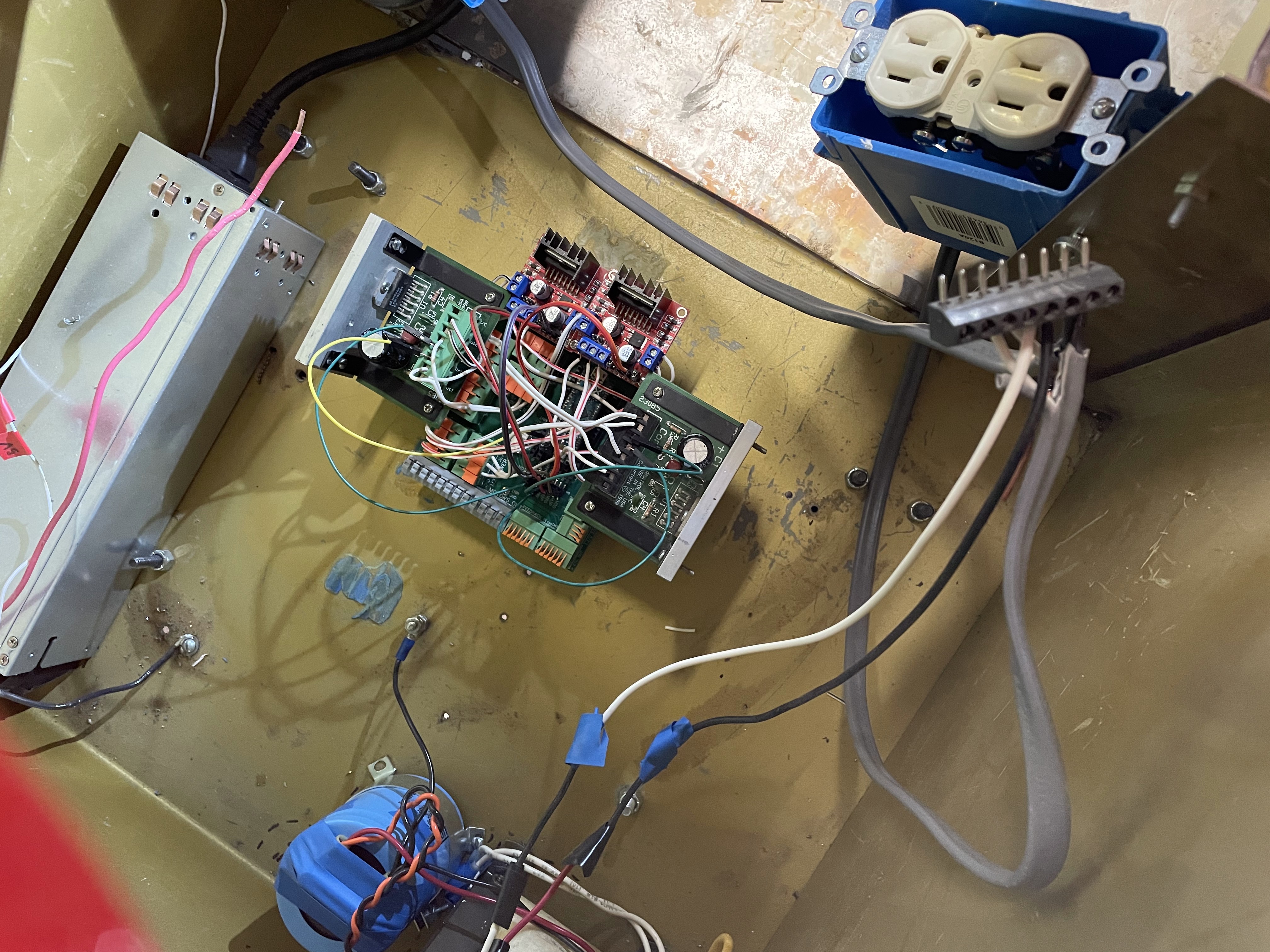
Top-down view of the same - compare to the top-down view of everything previously!
After this point, all of the prototype potentiometers were wired up. Next came the long and arduous task of fixing all of the bugs in the code,
rewiring some mistakes, and then tuning the PID loops on the arduino micro, which took user input and determined how to move to get the robot arm to where
it needed to be and keep it there. There are some videos of this process that will be added soon.
Importantly, though, the proof of concept for the control method worked, and was able to position-keep through its whole range of motion.
This brought up another problem, though: Because the proto-potentiometers that had been in place were made from nychrome foam-cutting wire, and were being
read across by rather not very well held on copper wires as wipers, there was a lot of jittering and wandering in the signal. It definitley did not help that
the longest wire of them all had a resistance of just 4 ohms. Shudder.
So. Some proper 10-turn potentiometers were ordered, and some mounts for them were 3D printed.
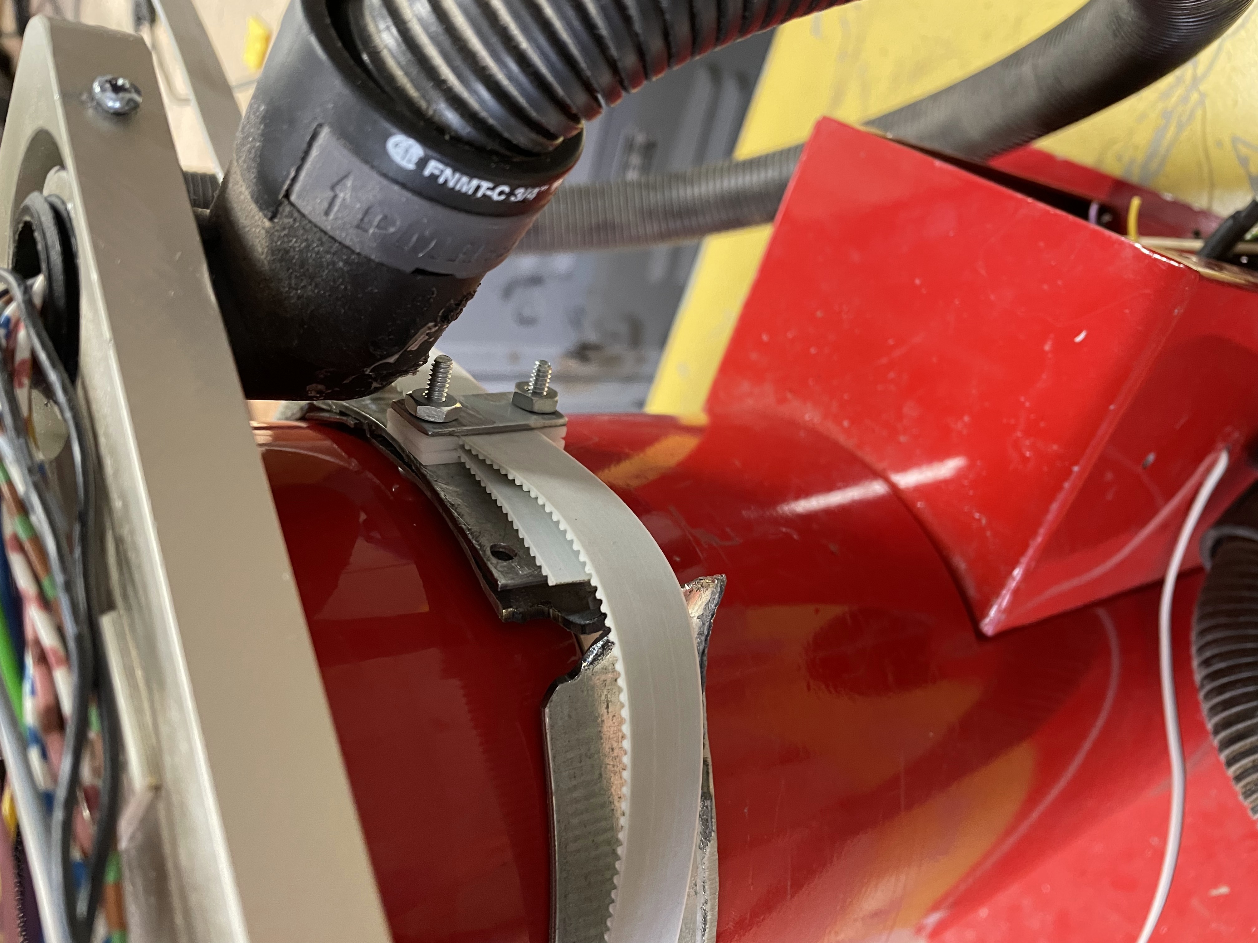
Here is the potentiometer for the first joint attached, with a belt for actuating it attached to a prototype ring.
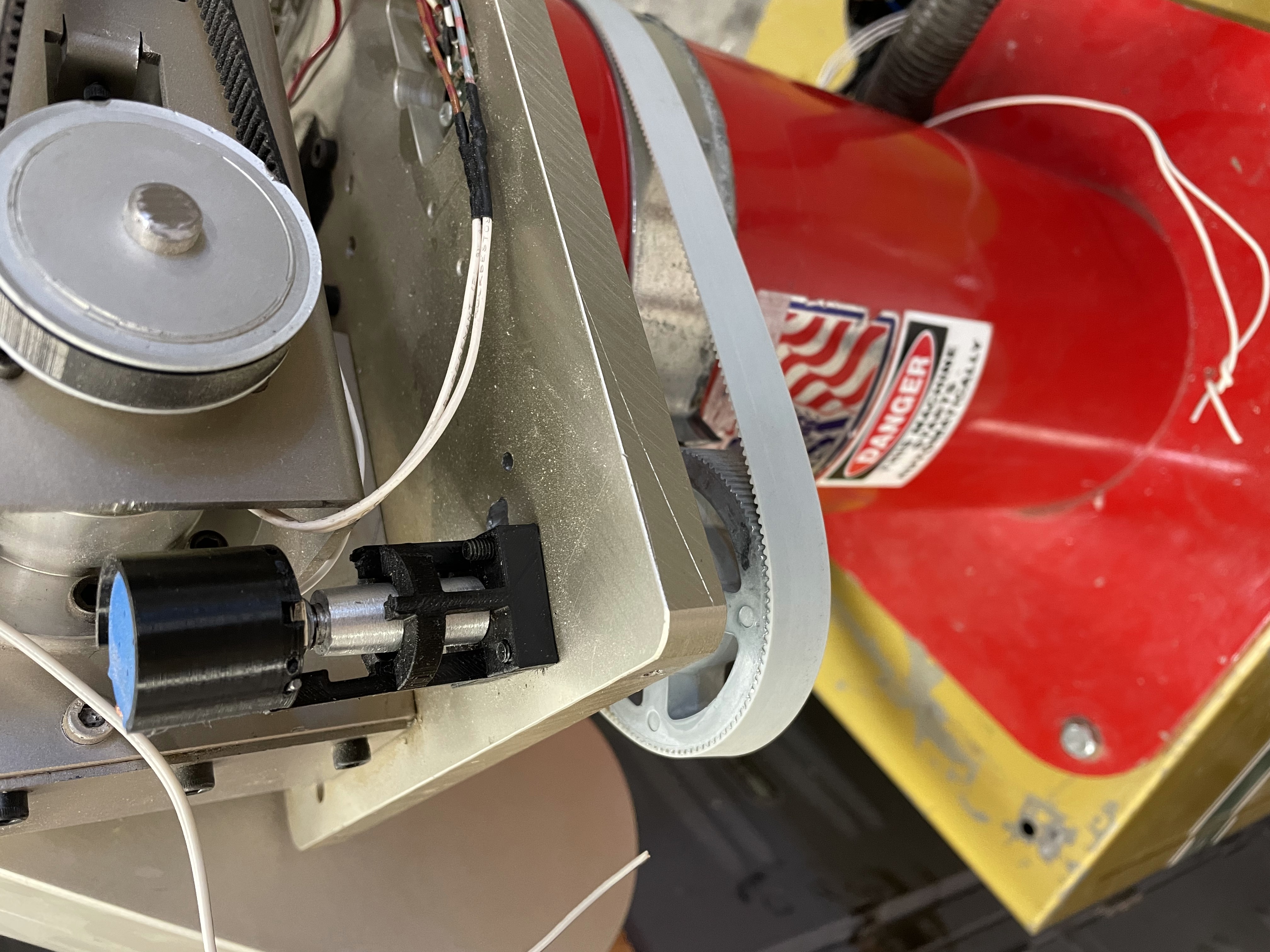
The prototype ring, however, did not have near enough clearance as was needed, which was fine, because it was just a prototype.
To solve the clearance problem, holes were drilled and tapped into the cosmetic portion of the trunk, as can be seen in the next few pictures, for the belt to be attached to.
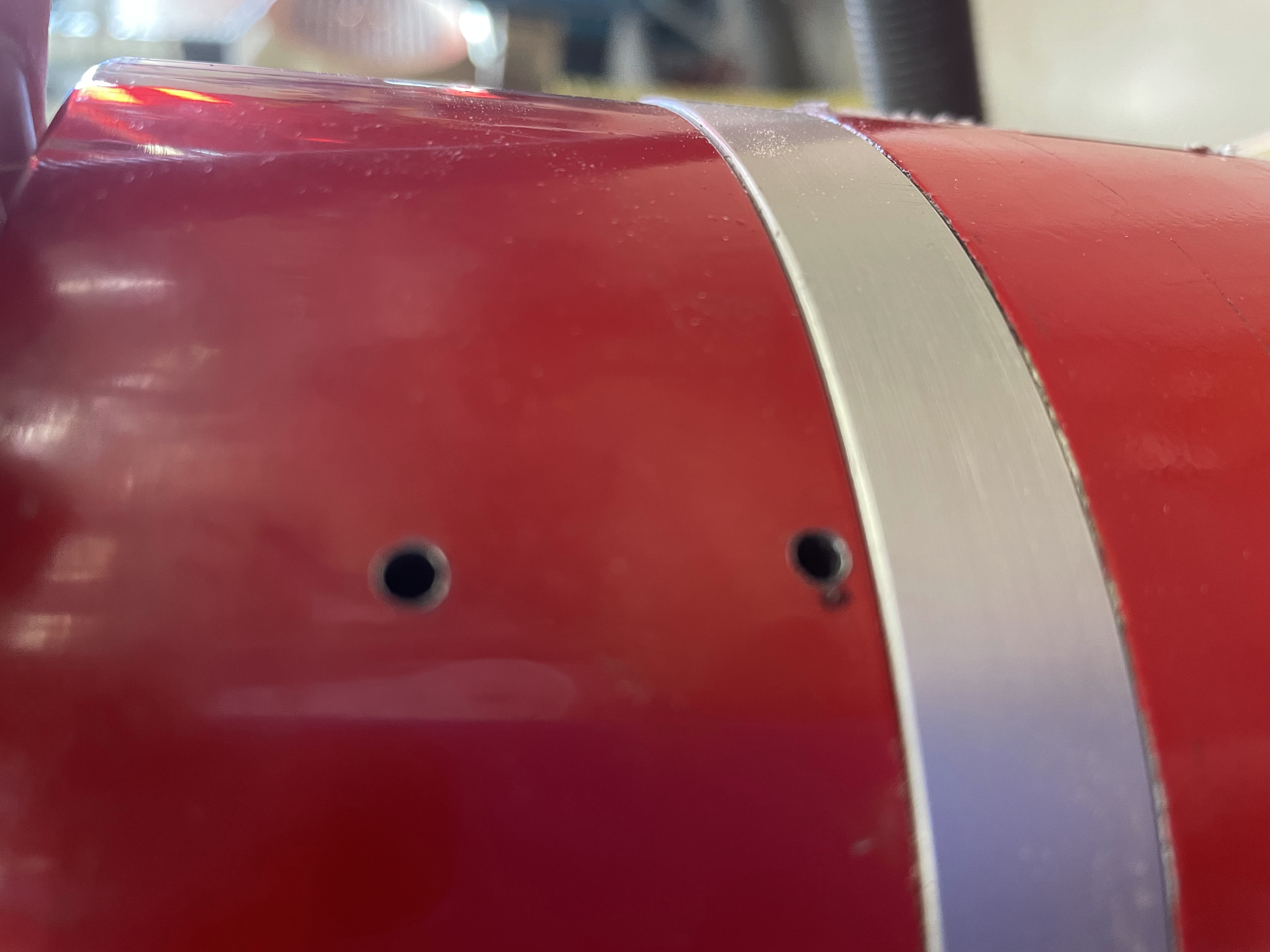
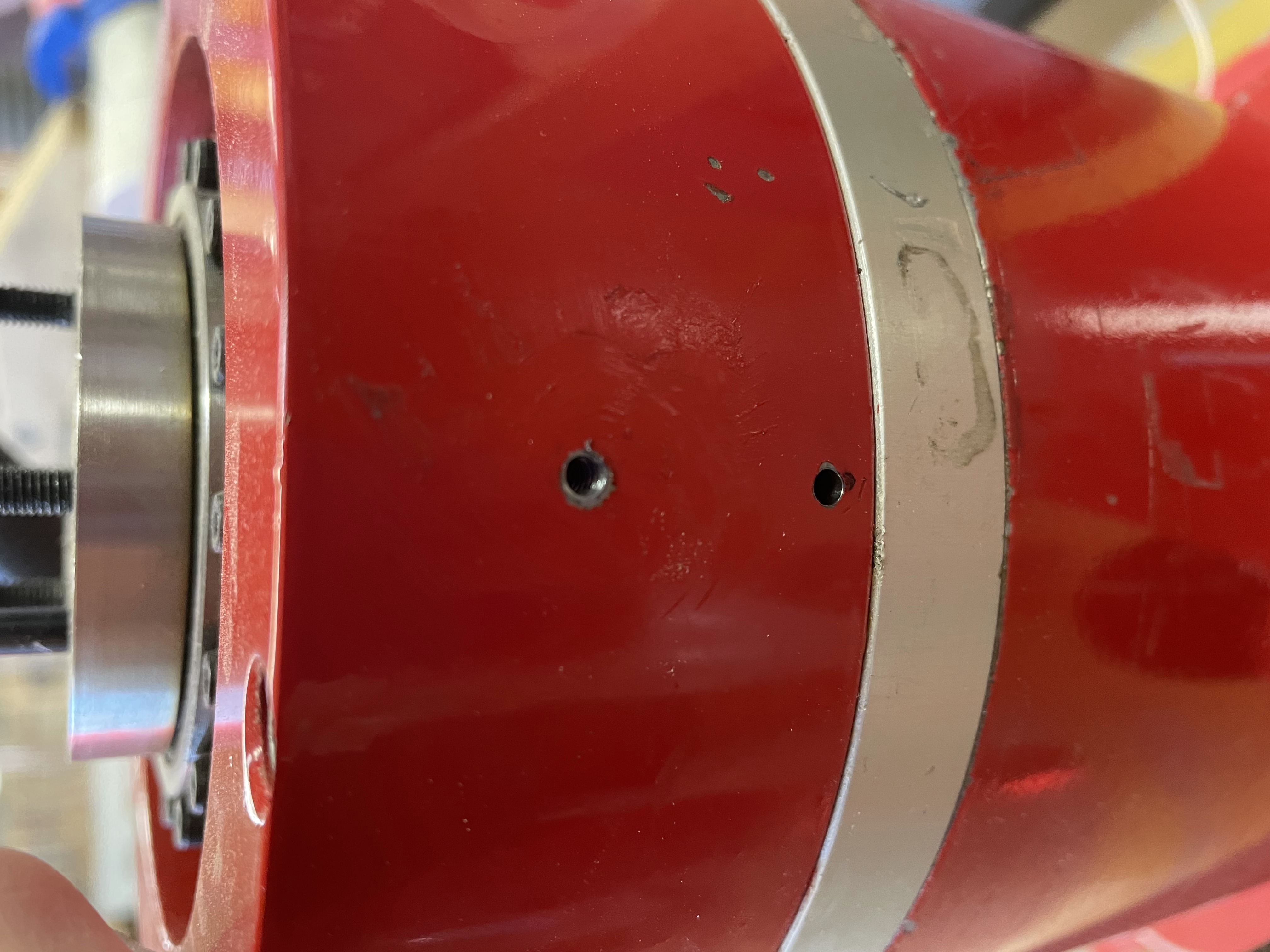
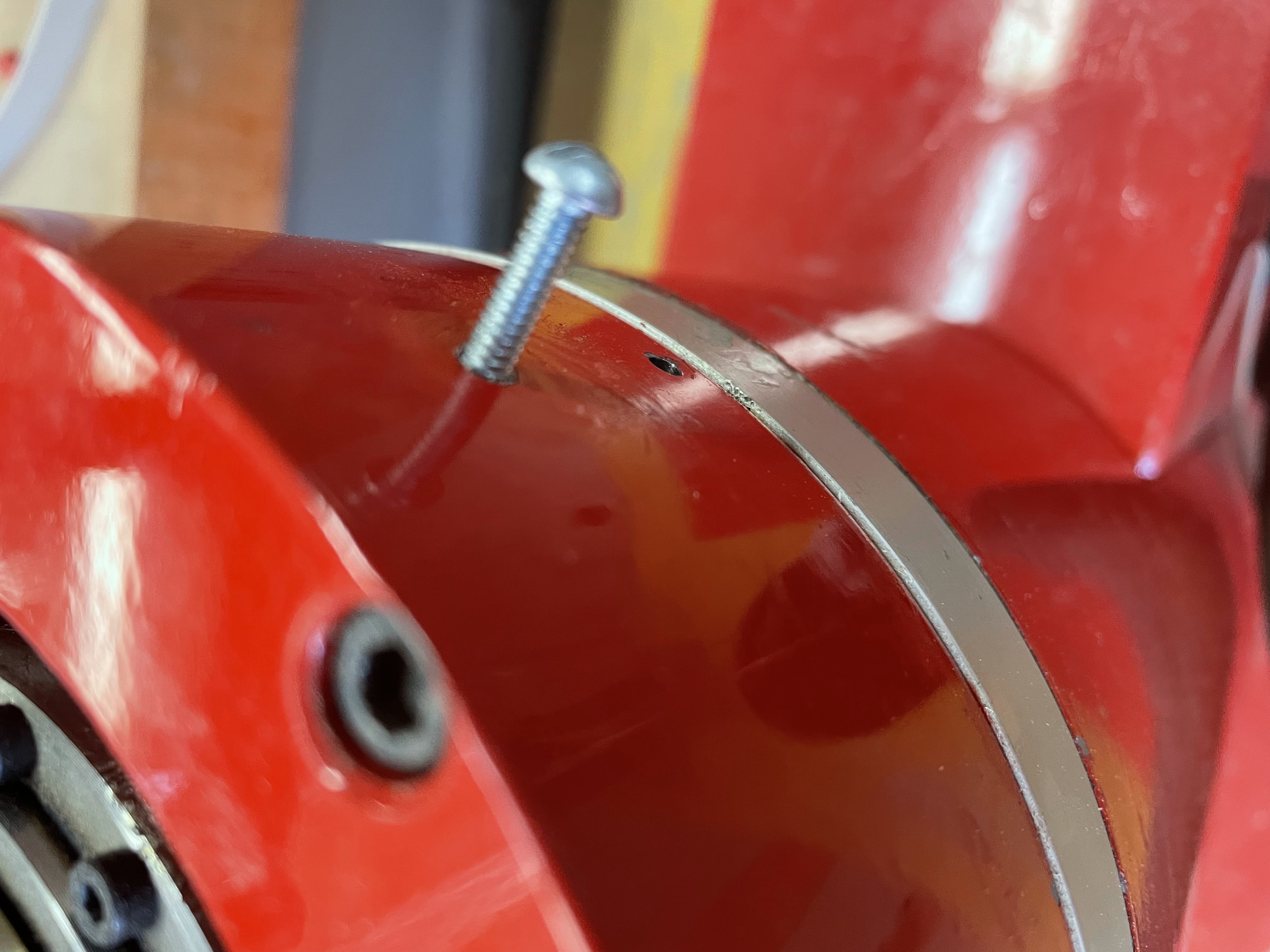
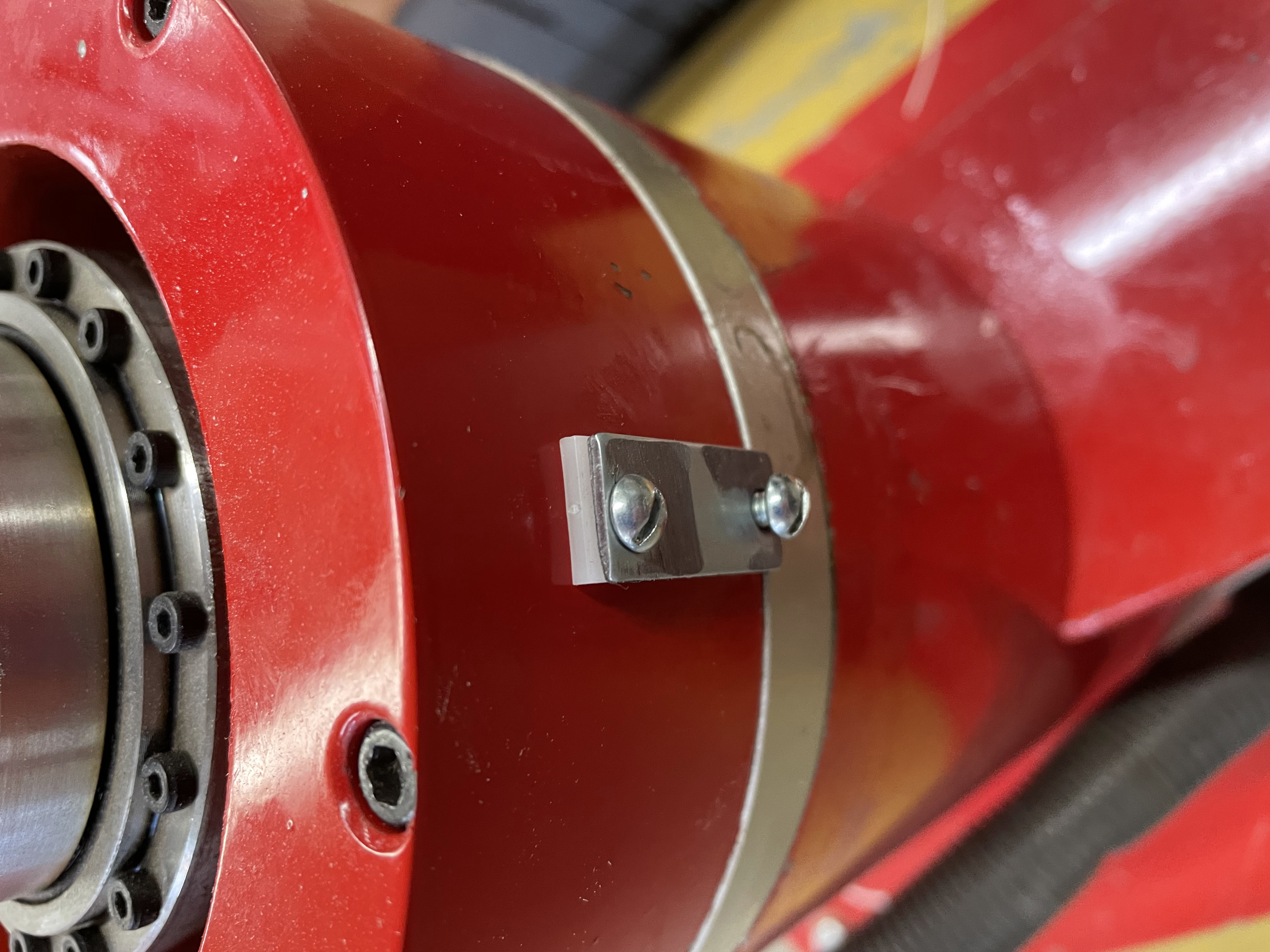
This solution was definitley low-profile enough.
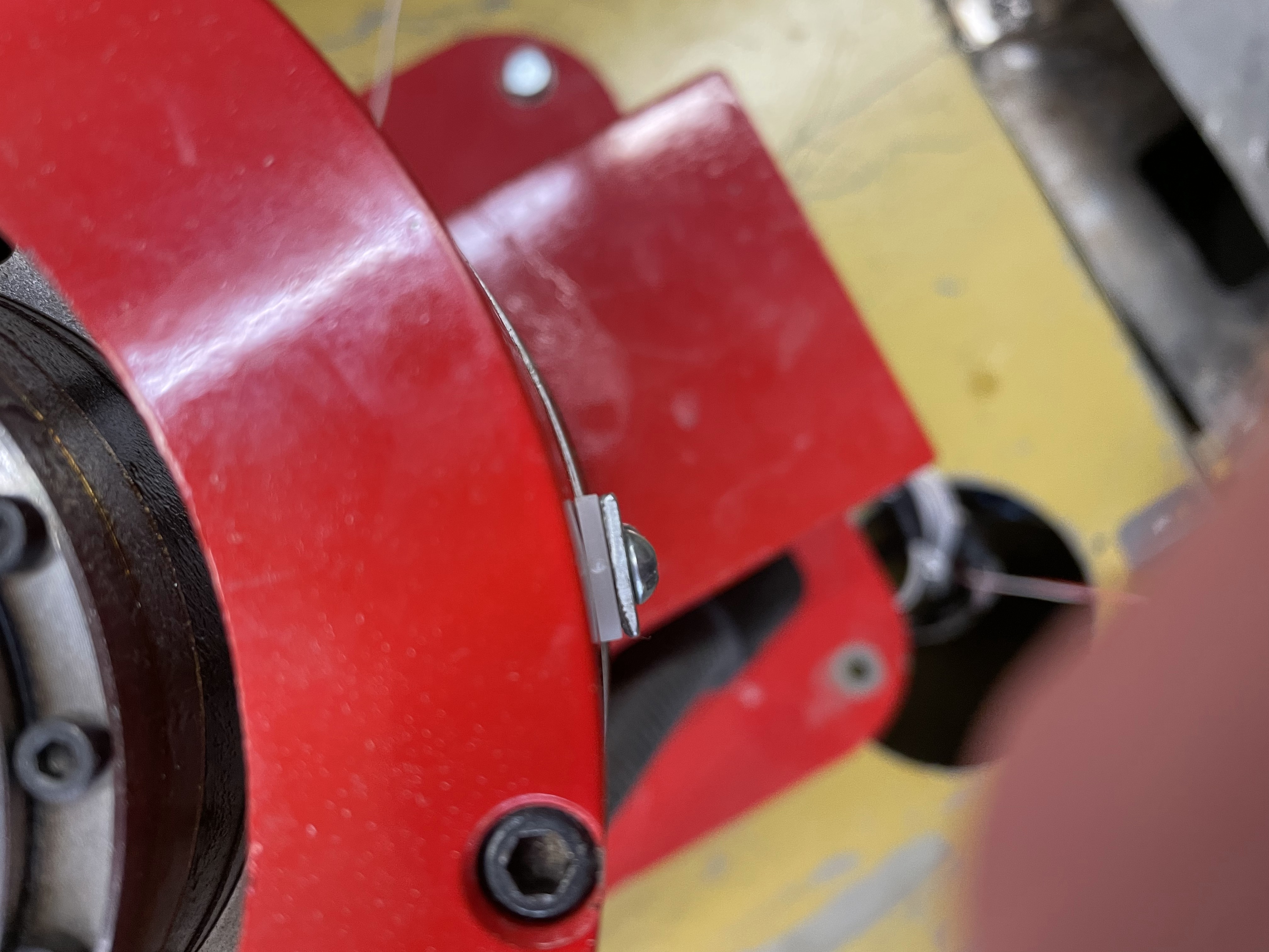
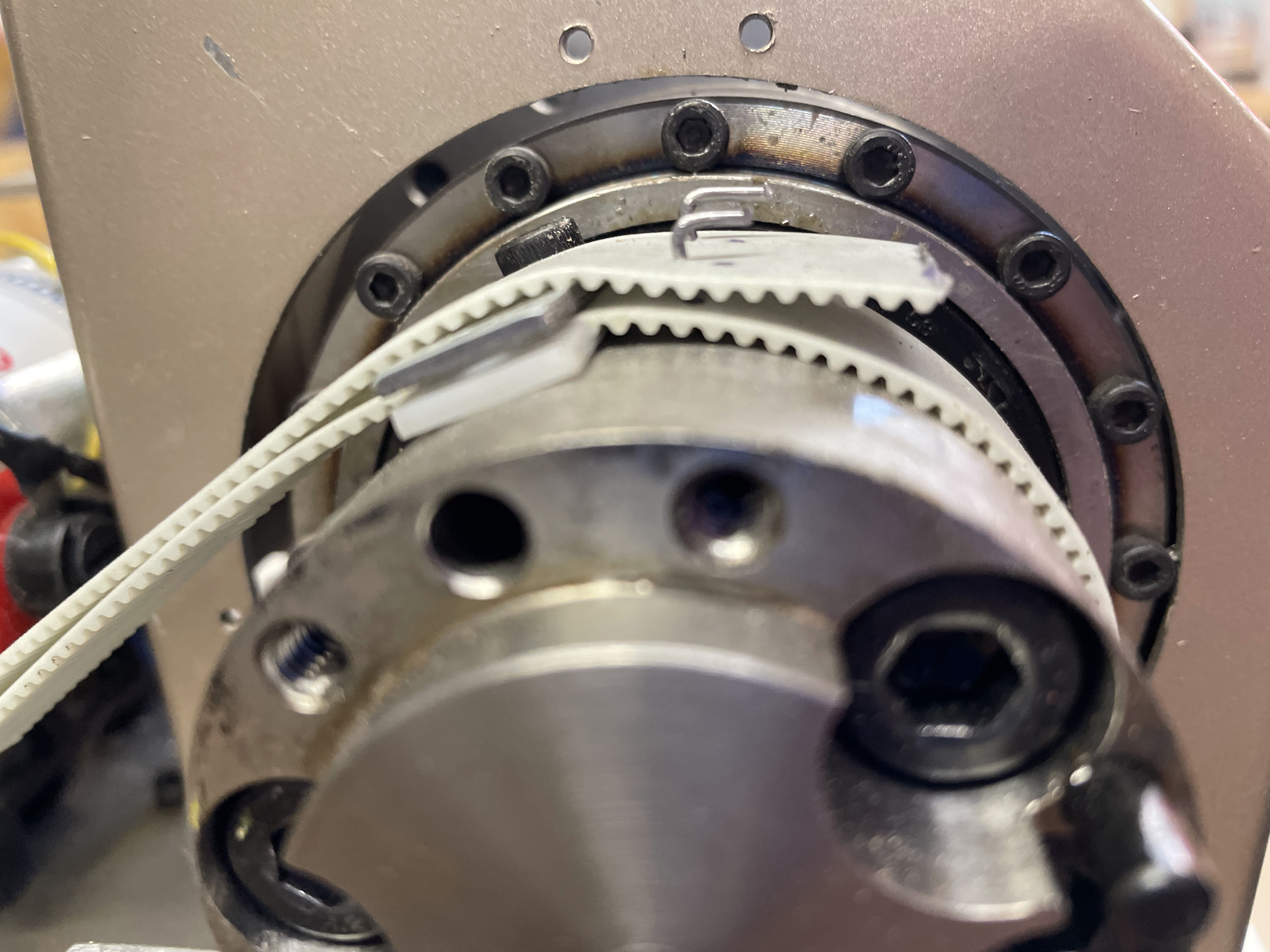
In this picture, the belt can be seen being attached to the second or shoulder joint, after holes were drilled and tapped in it.
Spring 2022
Major redesign is done. New belts are spliced. Better pulleys are 3D printed. Better gears are printed for the elbow and wrist joints. So much progress.
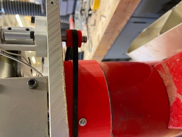
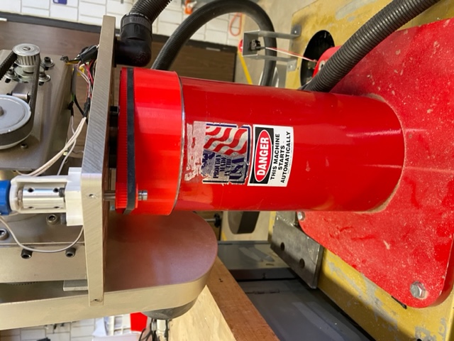
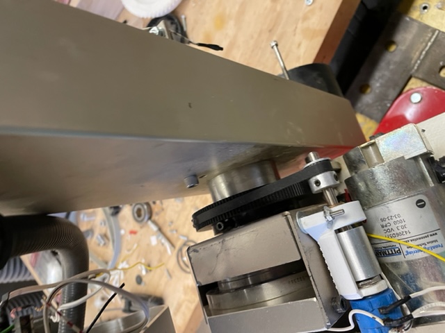
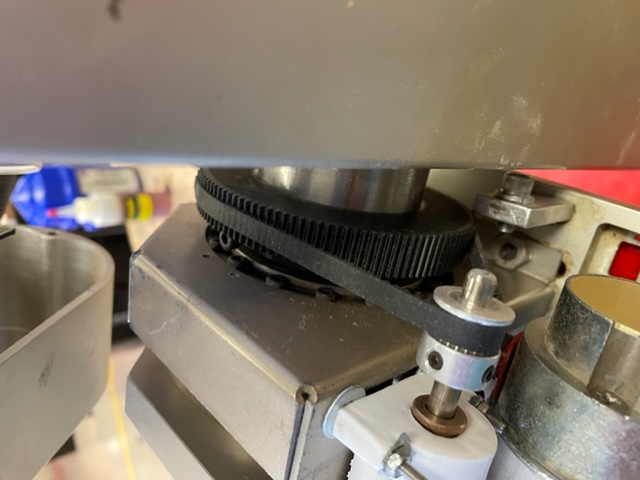
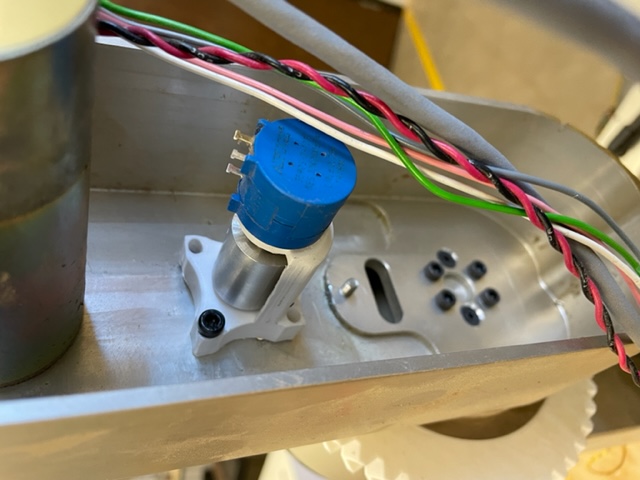
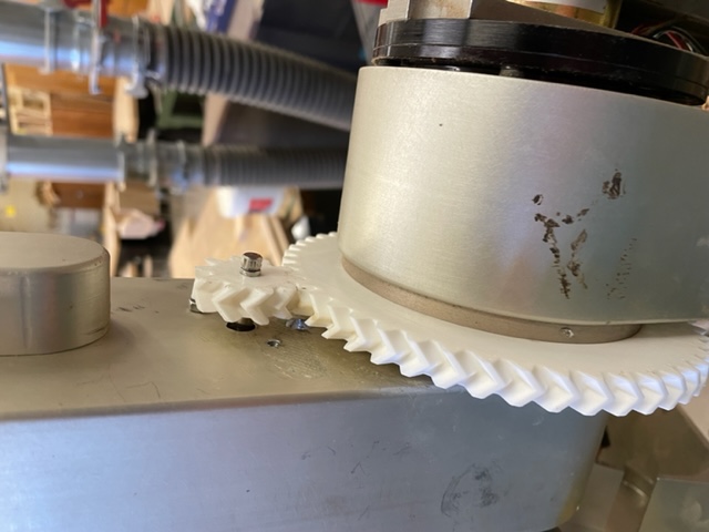
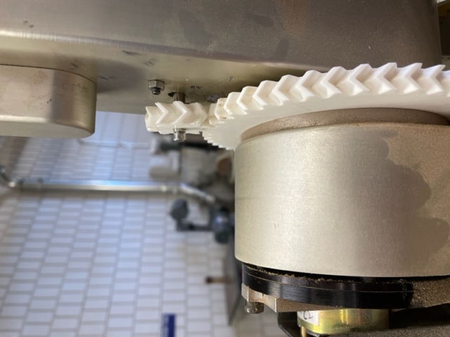
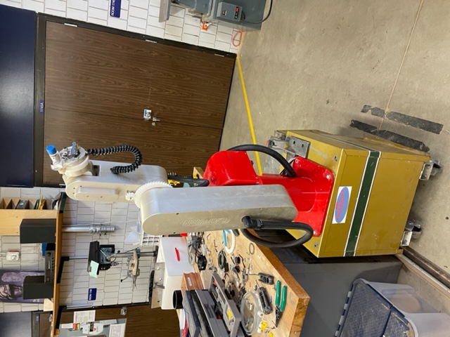
Finally, all the panels are put back on again, and the arm is ready for more PID tuning!
A delicious new machine arrives in the shop....
.jpg)
With the new CNC mill, aluminum pieces for a hand were manufactured.
.jpg)
.jpg)
.jpg)
The parts were cleaned and assembled onto the robot arm.
.jpg)
.jpg)
.jpg)
.jpg)
.jpg)
.jpg)
Some more wiring cleanup was also done, and a raspberry pi was installed alongside a network switch in the front half of the bottom compartment. This allowed for testing of the final control chain - A raspberry pi sitting on a desk, connected via ethernet and sending simplistic commands to a pi permanantly mounted inside the chassis, which handles the constant and somewhat annoyingly formatted data stream that the arduino nano needs to be able to interpret the data while still maintaining a low enough time per processing loop that the PID control does not fail.
That was pretty much all that was able to be completed before the end of the semester, but there is (finally) a video of the robot moving on its own, through a series of set positions on each joint. No motion smoothing or inverse kinematics had been done yet, so it is somewhat jerky and only moves one joint at a time, but it finally does move to where it is supposed to! The video cuts off before joints 3-5 can be seen, but they go through the same procedure flawlessly.
Video of first two joints!
September 2022
More tuning and API development was done, and the arm is fully functional, if somewhat cumbersome to code for. A program to pick up and continuously rearrange three small acrylic cubes was put together, to demonstrate simple interpolation and position cycling. Video of this program is here!
All that is left to do is to migrate all of the exisiting code into a single Python library, so that students can pip install it and be off and running with a few simple lines of code to initalize the arm. WOO!